Please contact email details to support@transpoco.com or call 00-353-19053881 to confirm installation and commission tracking unit.
Mechanical Installation
Select place of installation in a safe, dry and mechanically protected area. Avoid installation to places of direct sunlight and extreme temperature.
Install the device as far away as possible (minimum 1 metres recommended) from the radio antenna or other electrical devices to avoid any interference.
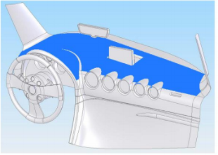
It is recommended to place GPS antenna behind the dashboard as close to the window as possible - see area in blue.
ECO 4 Light internal GPS
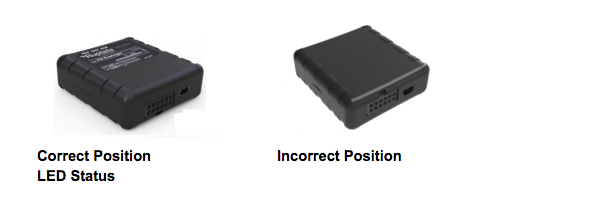
GNSS (GPS) status
Tables can't be imported directly. Please insert an image of your table which can be found here.
Status
No GPS
Blink every 400ms
Accurate GPS
Blink every 1s
GSM
Tables can't be imported directly. Please insert an image of your table which can be found here.
Status
No GSM
Blink every 200ms
GSM but no GPRS
Blink every 1s
GPRS connection
Blink every 4s
Install: 3 Wire
Tables can't be imported directly. Please insert an image of your table which can be found here.
Pin
Colour
Description
BAT +12/24V
Red
Constant Power
Chassis
Black
Ground
Din4
Yellow
Ignition
On completion please call Transpoco for testing and commissioning, +35319053881
You'll need the following information available to commission the unit:
- Install/service reference number starting ED,
- IMEI
- Vehicle registration number
- Mileage,
- Vehicle make
- Vehicle model
Install Extras
PTO
Tables can't be imported directly. Please insert an image of your table which can be found here.
Pin
Colour
Description
Din1
Pink
+ Digital Input 1
Din2
Blue
+ Digital Input 2
Din3
White
+ Digital Input 3
Driver Id
Tables can't be imported directly. Please insert an image of your table which can be found here.
Ruptela
Connect to
Description
Chassis (Black)
Driver Id reader Yellow and Gray
Driver Id Ground
1-wire DATA (Green/Yellow)
Driver Id reader White
Driver Id Data
Out 1 ( Purple)
- Buzzer (Black)
Buzzer Ground
1-wire PWR (Red/White)
+ Buzzer (Red)
Buzzer Positive
Private Mode
I Private Mode 0 Public Mode
Tables can't be imported directly. Please insert an image of your table which can be found here.
Pin
Colour
Description
Din 3
White
Digital Input 3
Constant Live